

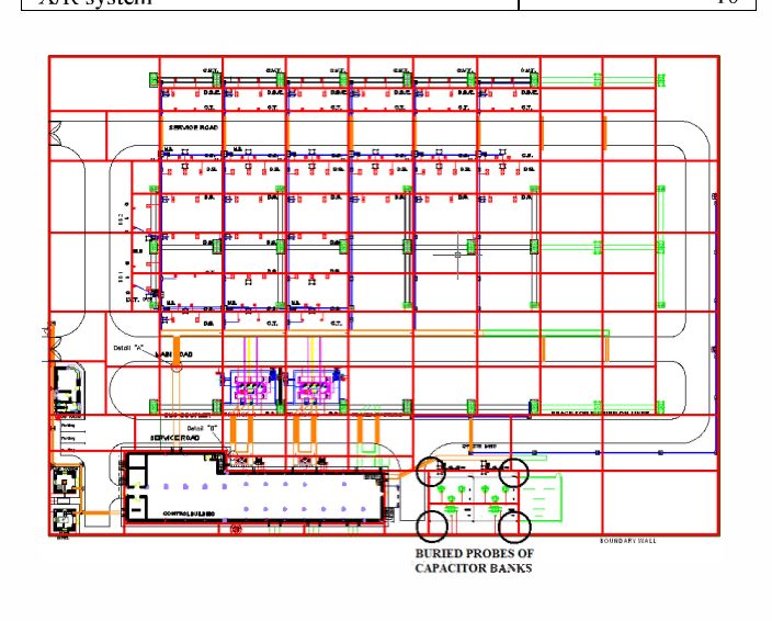
When designing high-voltage substations and large-scale
utility PV plants, the primary goal of an earthing system goes far beyond
equipment protection. It is a fundamental matter of human life and grid
resilience.
During a short-circuit fault condition, thousands of amperes
flow into the earth. If an earthing grid is under-designed or poorly simulated,
it results in hazardous Step and Touch voltages that can fatal to personnel and
catastrophic for sensitive electronic relays.
For international projects seeking financing or regulatory
approval, a simple compliance check is not enough. You need rigorous,
software-backed design validation.
Key Engineering Focus Areas:
- Why
empirical calculations fail in complex multi-layered soils.
- Controlling
Step and Touch potential boundaries under strict IEEE Std 80 and IEC
61936-1 protocols.
- How
advanced software modelling saves hundreds of meters of unnecessary copper
conductors.
1. The Critical Failure of Generic Soil Assumptions
Many basic engineering approaches treat soil as a single,
uniform block with a fixed resistivity value. In reality, soil is highly
stratified. A site might have a highly conductive wet clay layer just two
meters beneath a highly resistive layer of dry sand or gravel.
Our global design team utilizes Wenner Four-Pin soil
resistivity testing data provided by our clients to construct detailed
two-layer or multi-layer soil models. By accurately mapping the reflections of
fault currents across these distinct layers, we prevent the dangerous
under-sizing of the earthing grid that frequently causes project delays during
commissioning.
2. Taming Step and Touch Potentials (IEEE 80 vs. IEC
61936)
International jurisdictions follow distinct safety
boundaries. While the Americas and parts of Asia lean heavily on IEEE Std 80
(which uses specific body-weight metrics like 50kg or 70kg to determine
allowable shocks), European and Middle Eastern grids strictly mandate IEC
61936-1 and EN 50522.
Our design process ensures absolute compliance by
calculating:
- Touch
Voltage (Etouch): The potential difference between a metallic
structure and a point on the earth's surface separated by a distance equal
to a normal maximum horizontal reach (typically 1 meter).
- Step
Voltage (Estep): The potential difference between two points on the
earth's surface separated by a distance of one pace (typically 1 meter).
By strategically placing closely spaced conductors in
high-traffic operator zones and adding perimeter grading rings, we keep
calculated voltages safely below the maximum permissible thresholds.
3. Optimization: Engineering Out Unnecessary Copper Costs
Copper is one of the highest material cost drivers in a
substation or PV block layout. Over-designing a grid by simply throwing more
copper into the ground hurts your project’s bottom line.
Using advanced software simulation engines like CDEGS or
ETAP, our team performs iterative fault current distribution analysis. We
precisely calculate the Fault Current Split Factor (Sf)
which accounts for the current diverted away via overhead
shield wires or cable sheaths. By factoring in this reduction, we safely
optimize the grid mesh density, saving our clients thousands of dollars in raw
material and excavation costs without compromising safety.
[Soil Resistivity Data] ──► [Multi-Layer Soil Modelling] ──►
[Fault Current Split Calculation (Sf)]
│
[Verified Safe Earthing Grid] ◄── [Iterative Optimization
(CDEGS/ETAP)] ◄───┘